 by Steven D. Johnson
Racine, Wisconsin
This month:
The Ultimate Miter Saw Work Station – Finishing Up!
•
Building the Pedestal Bases
•
Adding the Roll-Out Trays and Shelves
•
Applying the Laminate Top
•
Installing T-Track, Inserts, Draw Catches, and More
The Ultimate Miter Saw Station – Stage 2 - Building The Rest
|
|
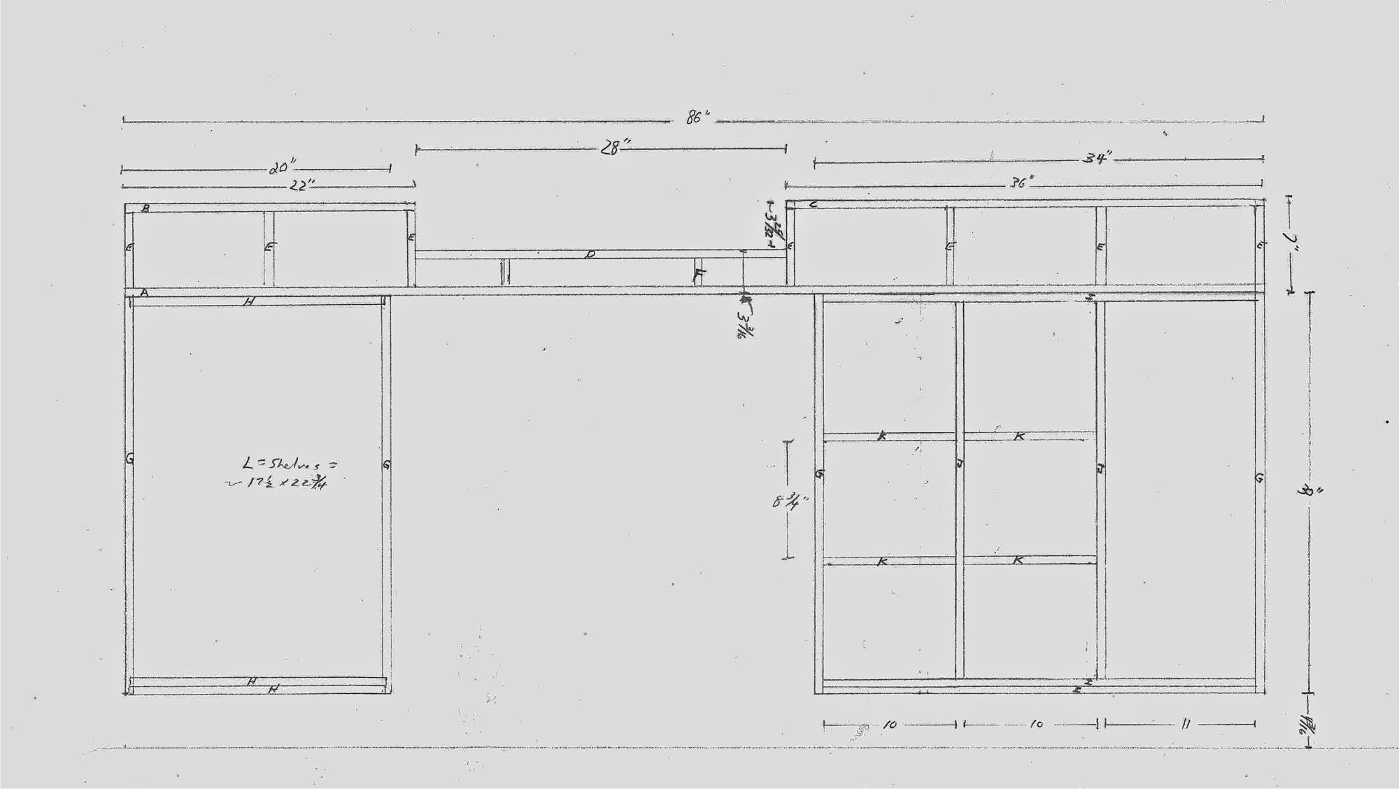
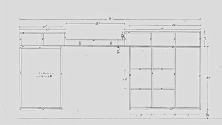
Figure 1 - Click on the plan to enlarge
|
With the
top portion of the miter saw workstation construction done
, attention turned to the base units. The two pedestal bases are built using 3/4" plywood with dados and rabbets. The bottoms consist of two sheets of 3/4" plywood, providing a rock solid anchor for the locking casters. Typically 3/4" plywood would also be used for the cabinet backs, but this time I used 1/2" ply, allowing myself just a "skosh" of extra interior depth.
The desire for extra front-to-back space was pure practical necessity. The plan was to make three rollout trays, each sized to hold two Festool Systainers, and the extra 1/4" was just what I needed to make sure two containers fit on each shelf.
After constructing the basic pedestal boxes, I attached the casters and then went to work adding the trim to obscure the plywood edges. Like all the other cabinets in my shop, I used commercially available, easy-to-work, and relatively inexpensive poplar. Once the edging was complete, I moved the top assembly onto the two base cabinets and got my first peek at how the project would look in its finished form.
This is the point in the construction of many shop projects where the detail work starts to slow down the appearance of visible progress. Of course there is progress, but it is not the big noticeable progress (and consequent feeling of accomplishment) that you get building a cabinet carcase. This is when regular visitors stop by the shop and wonder why you haven't been working for the past couple of days.
Adding The Roll-Out Trays And Shelves
|
|
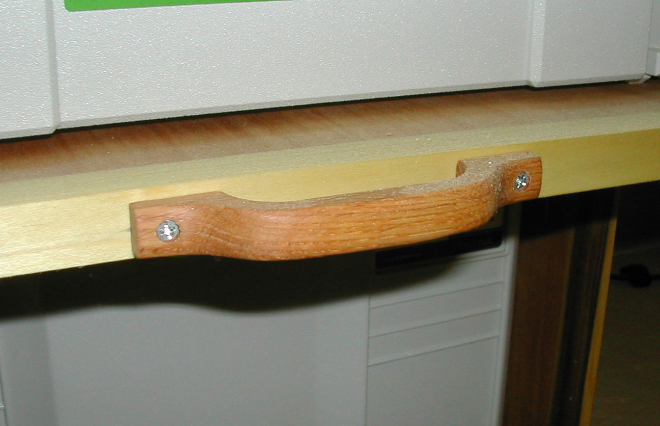
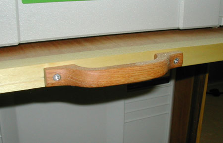
Figure 2 - Surface mount wood pulls
|
To complete the left side pedestal base it was necessary to make the rollout shelves and mount the drawer slides. Typical ball bearing slides were too tall for my plan to use 3/4" thick plywood as shelf stock. Instead, I used some inexpensive standard 3/4" extension bottom mount slides rated for 100 pounds. It was a simple matter to cut 3/4" plywood to size, face the front edge with poplar, and then mount the slides. I mounted the first set as close to the bottom of the cabinet as practical to still allow free movement of the shelf.

|
|
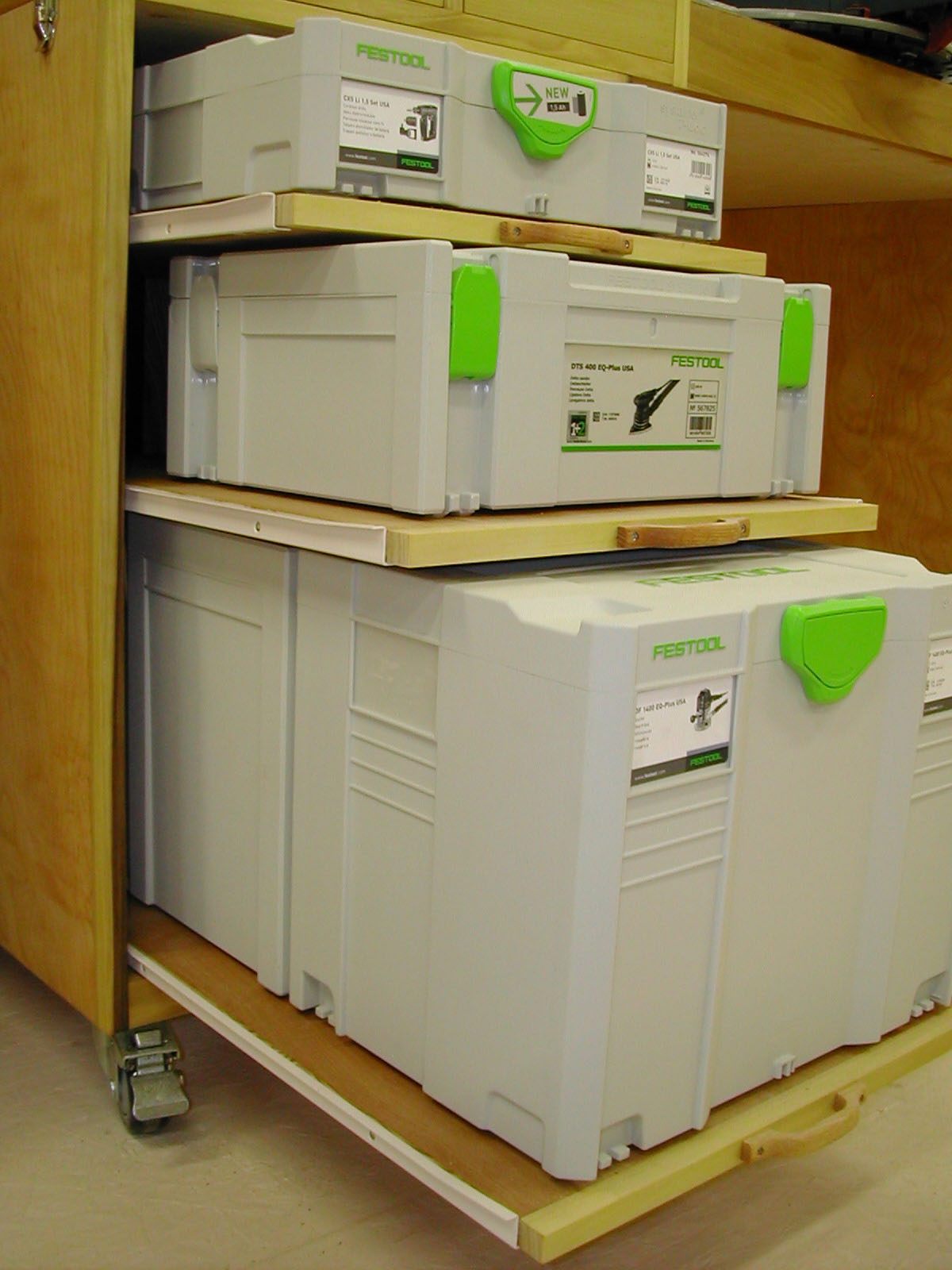
Figure 3 - Custom fit storage for my up to six Systainers
|
Then I placed my largest Systainers on that shelf and used them to position the next set of drawer slides. I worked my way up to the top, and when done, added some surface mount pulls that mimic the style of the other drawer pulls in my shop. I couldn't wait to see the fruits of my labor, so I stowed six Systainers and in the process picked up a few extra square feet of space in my shop.
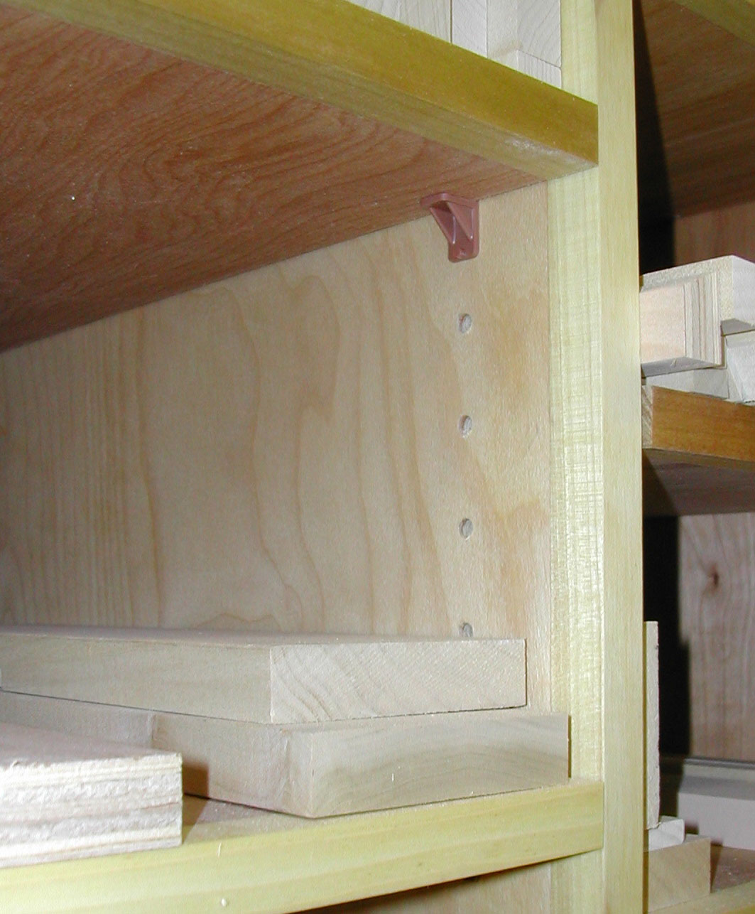
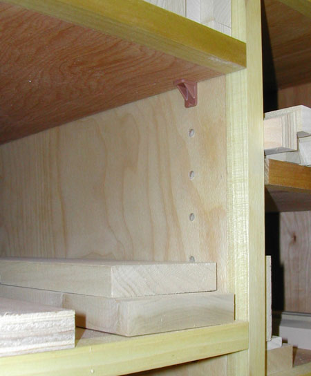
The cabinet on the right hand side was a bit more of a challenge. I wanted to use that cabinet for "shorts" or cut-off pieces of lumber and small bits of plywood and other detritus from my projects. A degree of "adjustability" was desired, so I decided on movable shelves and shelf pin holes using 1/4" pins. I have built a lot of cabinets and bookcases with rows of holes for shelf pins, but I have always drilled those holes on the drill press prior to assembling the units, using a "step and repeat" method. I have never drilled shelf pin holes "in situ" or "in place" after a cabinet was built.
|
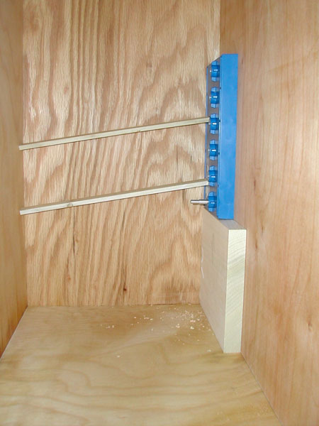
Figure 4 - Two thin scraps of wood make a
serviceable "tension clamp" to hold the jig in place
|
A buddy loaned me his Kreg shelf pin jig and after a little practice on some scrap material, it worked like a champ. The jig has metal inserts to guide the bit, straight and true, and a pin to register the jig in the last hole drilled as you move up (or down) the cabinet side drilling holes. The jig comes with a short brad point bit and a stop collar for setting the hole depth. Simply clamp the jig in place, drill 5 perfectly spaced holes, relocate the jig using the register pin, and continue drilling. In the back of the cabinet, there was no way to clamp the jig in place, so I wedged thin pieces of scrap into place to hold the jig – a sort of tension clamp.
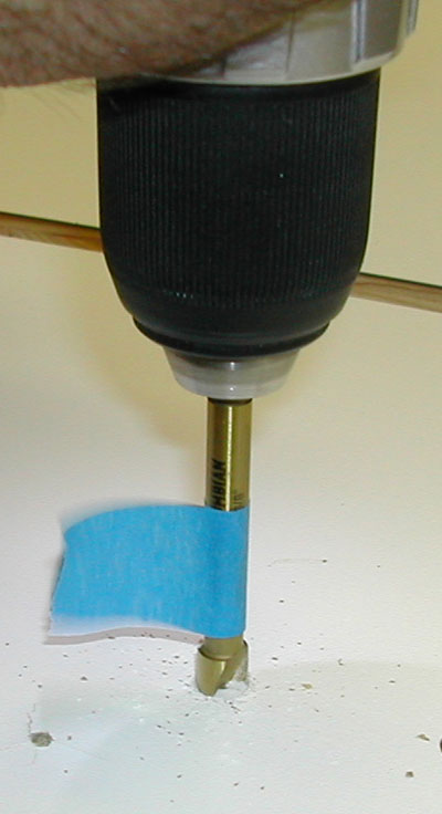
Space was a little tight inside the cabinets, but the
Festool CXS
came to the rescue, allowing me to drill precisely in those cramped quarters using the included right angle chuck. I made nine shelves, all of 3/4" plywood with the show edges faced with poplar. To make that process go a little faster, I ripped a sheet of plywood to a width equal to the front-to-back dimension I wanted, faced one edge, then after the glue was dry, cut the individual shelves from that one piece.
|
|
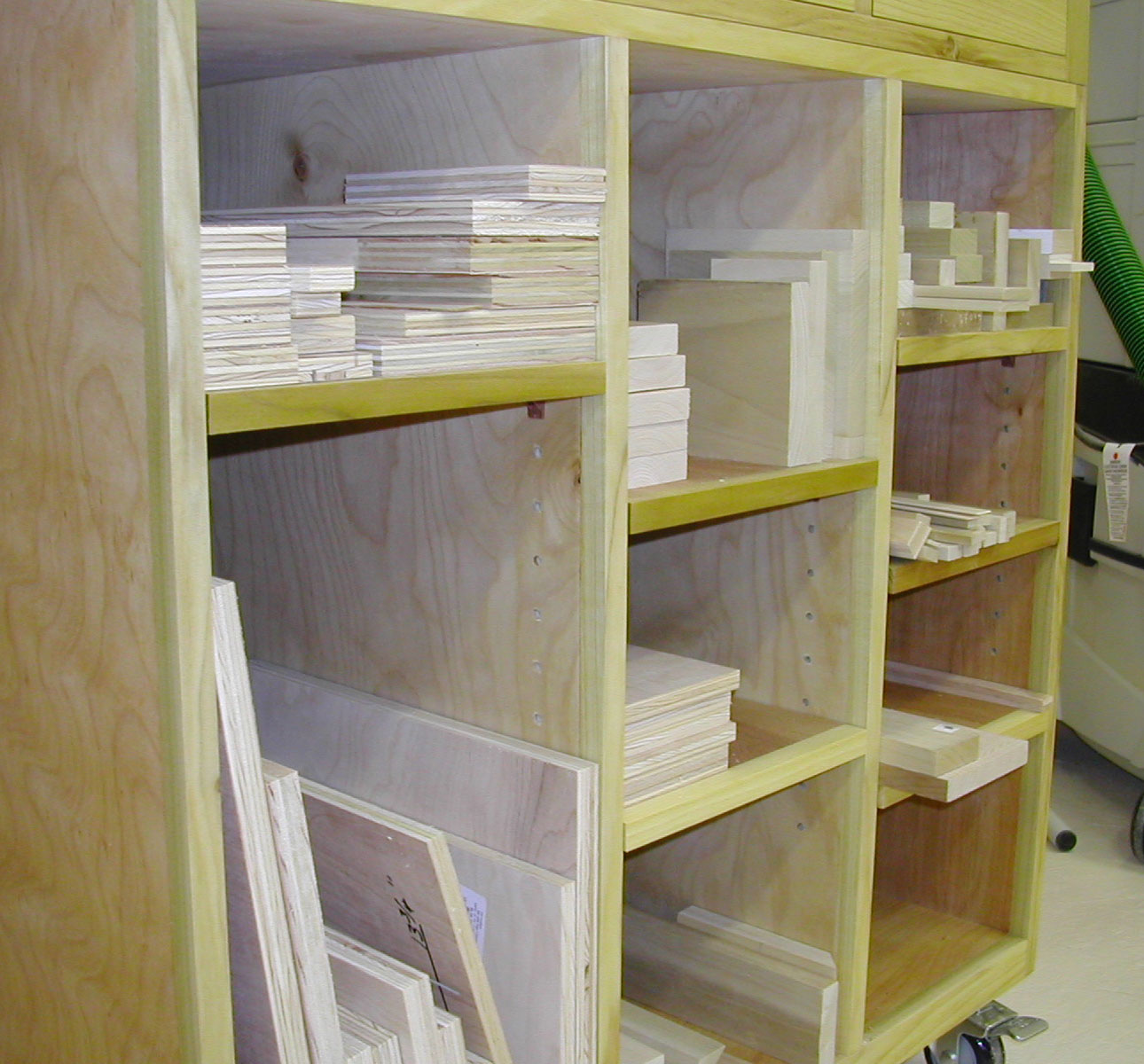
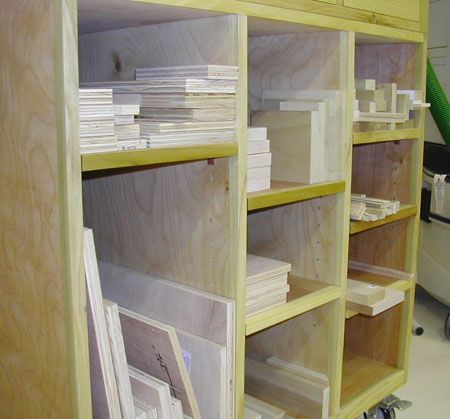
Figure 5 - Adjustable shelves accommodate a
changing collection of wood scraps
|
Figure 6 - I used plastic shelf pins,
but metal might be better
|
I randomly positioned the shelves initially, but with the shelf pins I will be able to adjust the height of the individual shelves as needed to accommodate my constantly changing collection of scraps.
Applying Laminate to the Top and Other Finishing Touches
Figuring I had procrastinated long enough, I set about performing some of the more challenging (at least to me) aspects of this project. The next steps were to apply the laminate top, then rout for the t-track, and finally, cut the t-track to size and mount it securely. Then I had to figure out a way to level and mount the miter saw itself and then secure the top assembly to the pedestals. Since all these things were relatively new to my repertoire of experience, I will share some of the tips and tricks I learned.
Applying laminate to the two raised left and right portions of the top was pretty straightforward. Simply cut the laminate a little oversize, apply cement to both surfaces and let it dry a bit, then roll and press the laminate into place. Later, clean up the edges with a laminate trim bit in a hand held router. The step I was obsessing over was applying laminate to the lower, or middle, section of the top. I simply could not figure out how I was going to get the left and right side edges that adjoin the higher sections straight and tight, and how I would get the front and back edges of the laminate trimmed flush. No doubt the router base would run into the rest of the cabinet leaving a couple of inches of untrimmed laminate at each end of the front and back of the center top assembly.

|
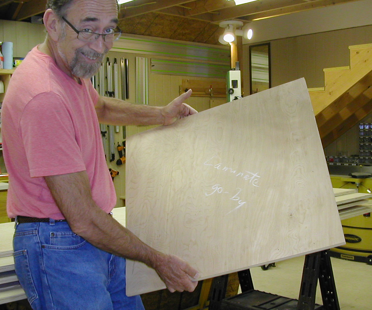
Figure 7 - A proxy piece, or "go-by" was used to pre-trim the laminate
to size before gluing it to the middle section of the top assembly
|
I could cut the laminate as close as possible for the left and right-hand sides, leave the front and back oversize, glue it in place, and then trim the front and back with the router...or at least part of it, until the router base base hit the elevated sides. Then I would have to cut the rest of the laminate as close as possible and file it to fit. This seemed like a lot of work fraught with potential for mistakes and ugliness to creep in.
After much "noodling" a dim CFL bulb went on, and I realized I could make a "proxy" for the top, or as I called it, a "go-by." I cut a piece of 3/4" plywood to the exact...and I mean exact...size of the lower, middle section of the top. I then used clamps to hold a piece of laminate in place on my "go-by" and trimmed it flush around all four sides with the router. That perfectly sized piece of laminate was then fairly easy to glue into position, eliminating the need for post-installation hand or router trimming.
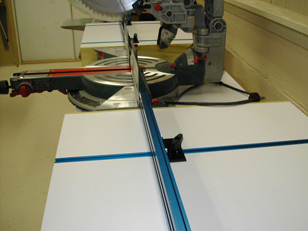
Routing Grooves for the T-Track

|
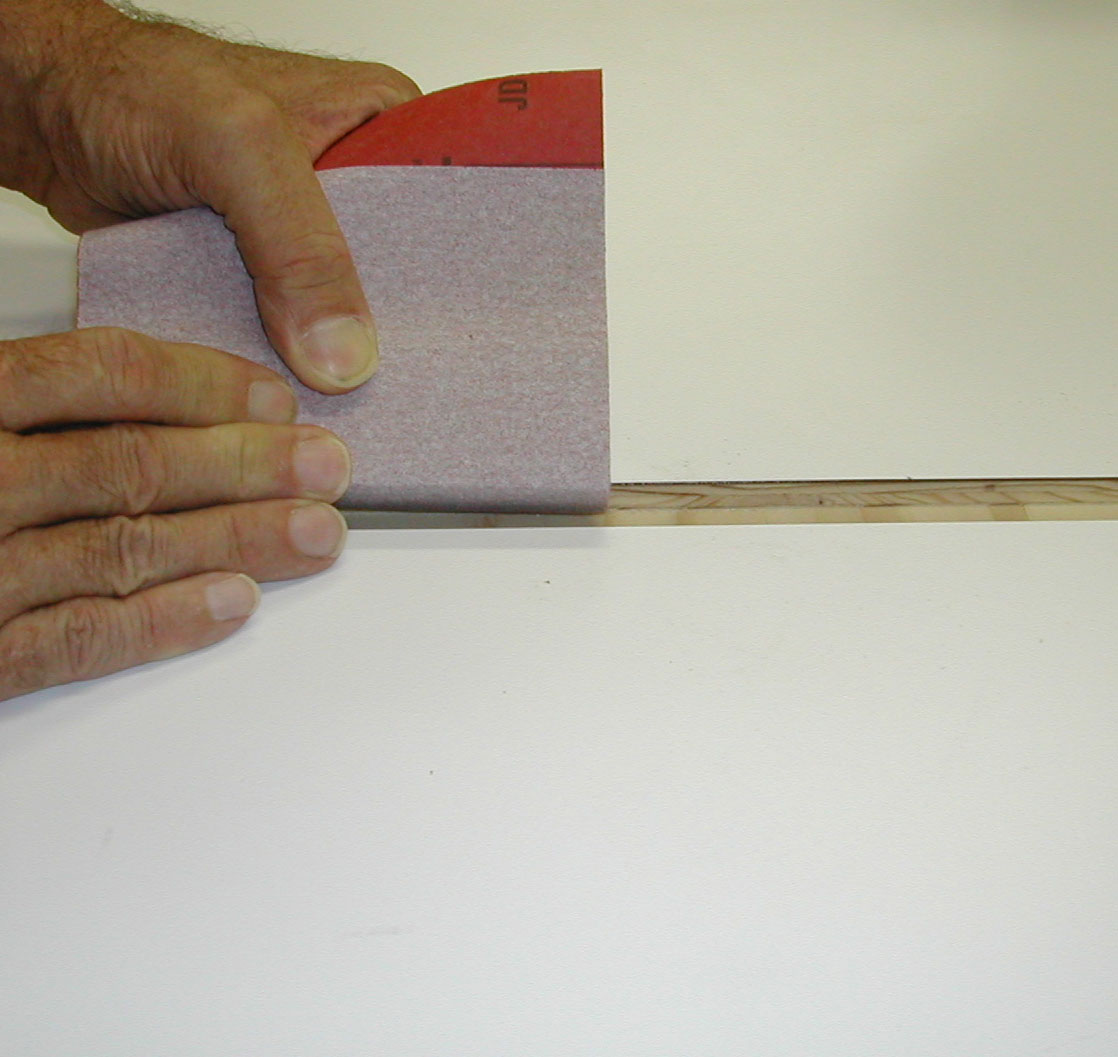
Figure 8 - Sandpaper and a light touch smoothed the edges
of the laminate top on either side of the miter slot grooves
|
With the laminate applied, the next step was to rout the grooves for the t-track. I've routed miles of grooves, but never through a laminate-covered surface. I was worried about chipping and tear-out. Rather than risk messing up the top of the assembly at this late stage of the game, I grabbed a piece of plywood I had used previously to make some test dado cuts and covered the opposite side with laminate. I then set up the
Festool Guide Rail
and
OF 1400 Router
with a 3/4" straight bit and made a test cut. One inch in, I realized my results were going to be less than stellar. I fiddled with the speed and depth of cut, and eventually arrived at a technique that gave me good results. It was a combination of a down-shear bit, a fast bit speed, a full depth of cut, a single pass, and a hopeful spirit. After all the test cuts and practice, I was still a little nervous, but the smooth running and rock-solid Festool router and Guide Rail gave me confidence and the cuts turned out fine.
Even though the grooves were perfectly clean with no chip-out, I did "relieve" the edges of the grooves a bit with sandpaper wrapped around a small block --- just a couple of careful swipes with the block held at a 45-degree angle. This made the cut edges of the laminate "pretty" and helped when inserting and removing the t-tracks during their cutting and fitting phase. The small chamfered edge assured there was no chance of the t-track catching on the laminate and lifting it up or splintering it.
Cutting and Fitting the T-Track
I can cut a dovetail by hand and saw a fairly straight line, and sometimes make respectable tenons with a handsaw. But sawing metal with a hacksaw has always intimidated me a bit. It is probably just an irrational mental block, but after all this work, I really wanted the t-track to have a clean cut and to look professional.

|
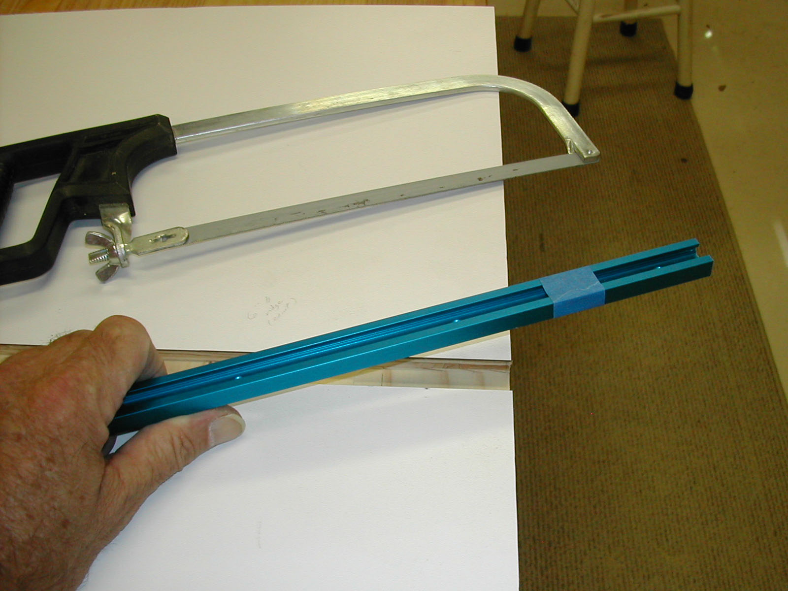
Figure 9 - The blue painter's tape provided a
very visible saw line and helped guide the cut
|
First I went to the local hardware store and bought the most expensive new blade I could find for my hacksaw...I think it was two dollars versus the one-dollar alternative. Truthfully, the "premium" price did not instill much confidence.
I placed a section of the t-track in a groove on the miter stand top and marked the exact cut location using a razor knife. After carefully removing the t-track from the groove, I wrapped blue painter's tape around the stick, the edge of the tape dead even with my cut line. Then the t-track was placed in the test groove I had cut earlier in my test board and I clamped the whole thing to my bench. With dread and uncertainty I took a deep breath and started to saw...slow, long, even, straight strokes...letting the saw do the work. I patiently followed the edge of the painter's tape and held the cut as straight as possible. Eventually I got through it, and after removing the tape, I had a pretty clean cut that required only a light touch with a rattail file to remove some sharp bits of metal. This procedure had to be repeated four times for the t-track and twice more for the fences. Maybe next time I will have a bit more confidence with my ten dollar hack saw and its premium two-dollar blade!
The t-track was pre-drilled every few inches along its length and the holes were chamfered, so I opted for #4 X 5/8" wood screws to mount the track in the grooves, no glue necessary. Unless my
tool torturing relative
uses my miter saw, the tracks should stay in place.
Mounting the Saw
|
Figure 10 - A regular clamp-on
depth stop could mar the laminate
surface... painter's tape works
great as a visual depth stop
|
With the t-track installed, I finally moved the miter saw from its temporary perch atop 2 X 6's and sawhorses and into place in its new home. The left-to-right and front-to-back fit was predetermined, but if the height of the two adjacent work surfaces was going to be "off," it was critical that they be too high, not too low. As planned (and hoped), they were a couple of hundredths too high, so leveling the saw with the work support surfaces was the easy next step. I used a solid reference straight edge and some automotive-type feeler gauges and determined the shim thickness needed. That done, the only question remaining was how to attach the saw to the top assembly.
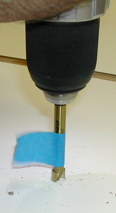
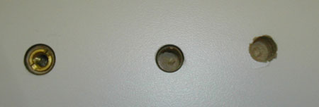
I could drill holes all the way through the top and bolt the saw down, but that seemed a bit brutish and likely was overkill. I decided to use threaded inserts in the top. Once again the laminated top presented a challenge...how to drill for and install the threaded inserts without making a mess.
Back to my now well-used test board, I tried first simply drilling a hole of the correct size with a brad point bit. The resulting hole had a raised and chipped bit of laminate all the way around, and I wouldn't swear in a court of law to the perpendicularity of the hole. In fact, when I tried to screw an insert into the hole, it started crooked, stayed crooked, and further raised the laminate up around the edges of the hole. All in all, it was pretty ugly.
I switched to a Forstner bit. The sharp tip made positioning the bit a breeze, and the circular cutters helped me line up the bit perfectly straight --- when the circular outside cutter is cutting all edges at the circumference of the hole at the same time, the bit is straight. If the bit is digging into the work piece more on one side or the other, the bit is crooked.
|
|
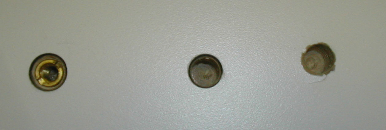
Figure 11 - The hole on the right side was my first attempt...ugly!
|
To make sure I didn't drill too deeply, I put a piece of painter's tape around the drill bit shaft at the depth I wanted, and when the floppy end of the tape started wiping away the sawdust, I knew I was at the right depth.
The Forstner bit solved the problem of the drill bit raising the laminate up, but installing the insert still caused the same raised and cracked laminate edges. I decided to chamfer the hole a bit using a large countersink, and that solved the problem. Actually, chamfering the edges of the hole made the whole thing a little prettier.
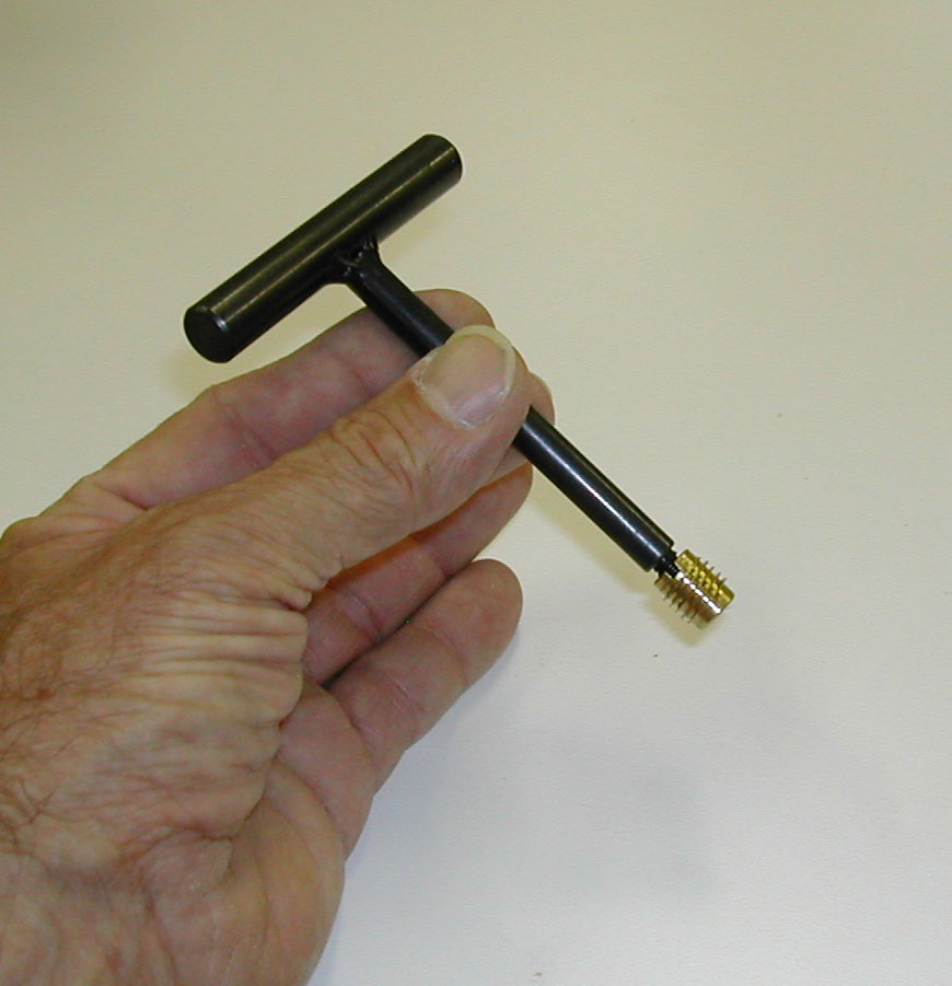
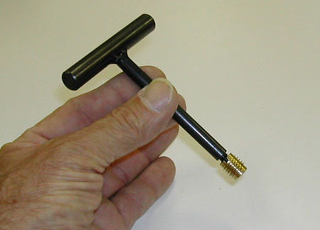
When installing inserts, be sure to use the right tool. The
threaded insert tool
is just $5.99 and will insure a neat clean job with minimal effort.
With the inserts installed, I used a wing knob with a 1" long stud to secure the miter saw.
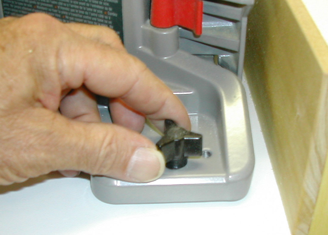
|

|
Figure 12 - Threaded insert tool is ingenious,
easy-to-use, and inexpensive
|
Figure 13 - Four wing knob bolts secure the
miter saw to the workstation
|
As a side note, I drilled and installed two sets of threaded inserts so that the saw could be mounted in two positions. Probably 95% of my cuts on the miter saw are made in material less than six inches wide. Mounted in the forward position, the saw handles that width easily, and is more accessible and comfortable. On the rare occasion when I need to crosscut a 10 or 11 inch board, I can slide the saw back into its rear position, fasten it down in the second set of inserts, and the work tables will then support a very wide work piece.
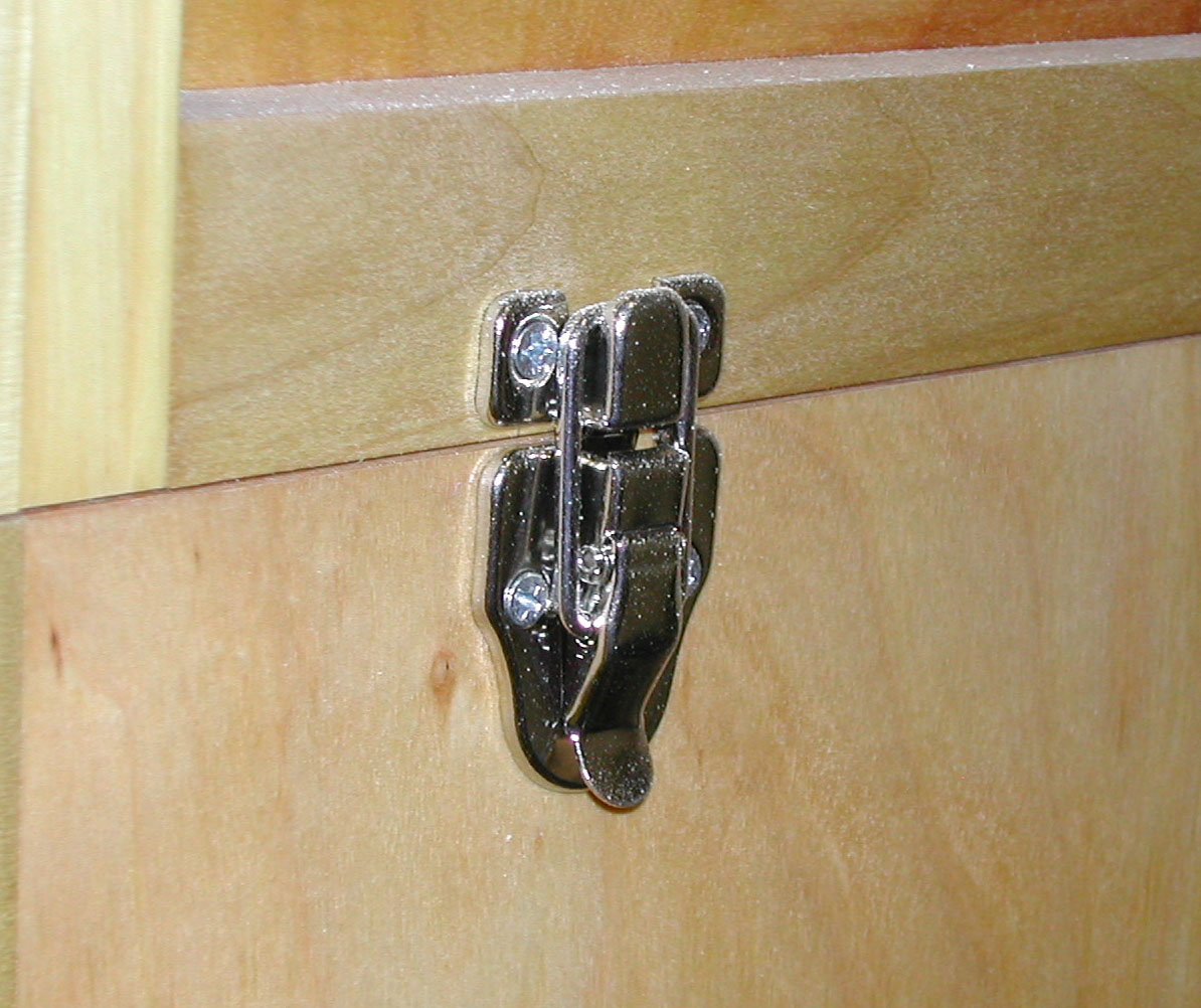
Attaching the Top to the Base Cabinets
|
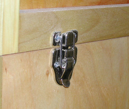
Figure 14 - Draw catches secure the
top assembly to the pedestal bases
|
As originally listed in my design specification, the top needs to be removable from the two pedestal bases, and while the weight of the top assembly and the saw itself rendered the top rather immobile on the bases, I wanted a bit more security. Draw catches, like you might use on a box or chest, turned out to be the answer. They were cheap and are functional. I placed four draw catches on each pedestal and have since moved the entire work station a number of times and used the saw a lot. There has been no movement of the top on its two base pedestals.
First Cuts, First Impressions
Functionally, the saw is no different than it was on top of 2 X 6's and plastic sawhorses. At least intuitively that would seem to be the case, but somehow the whole thing seems sturdier, less noisy, more substantial, smoother...well, just better. And it may well be. Mass dampens vibrations and damped vibrations dampen noise. This miter saw stand has a lot of mass. Figure four sheets of plywood at about 60 pounds per sheet, an almost one hundred pound saw, hardware, casters, laminate, and whatever is in or on all those shelves, roll-out trays and drawers, and it adds up to a lot of weight. Couple that with a sturdy build, and vibration and noise are significantly reduced.

|
|
|
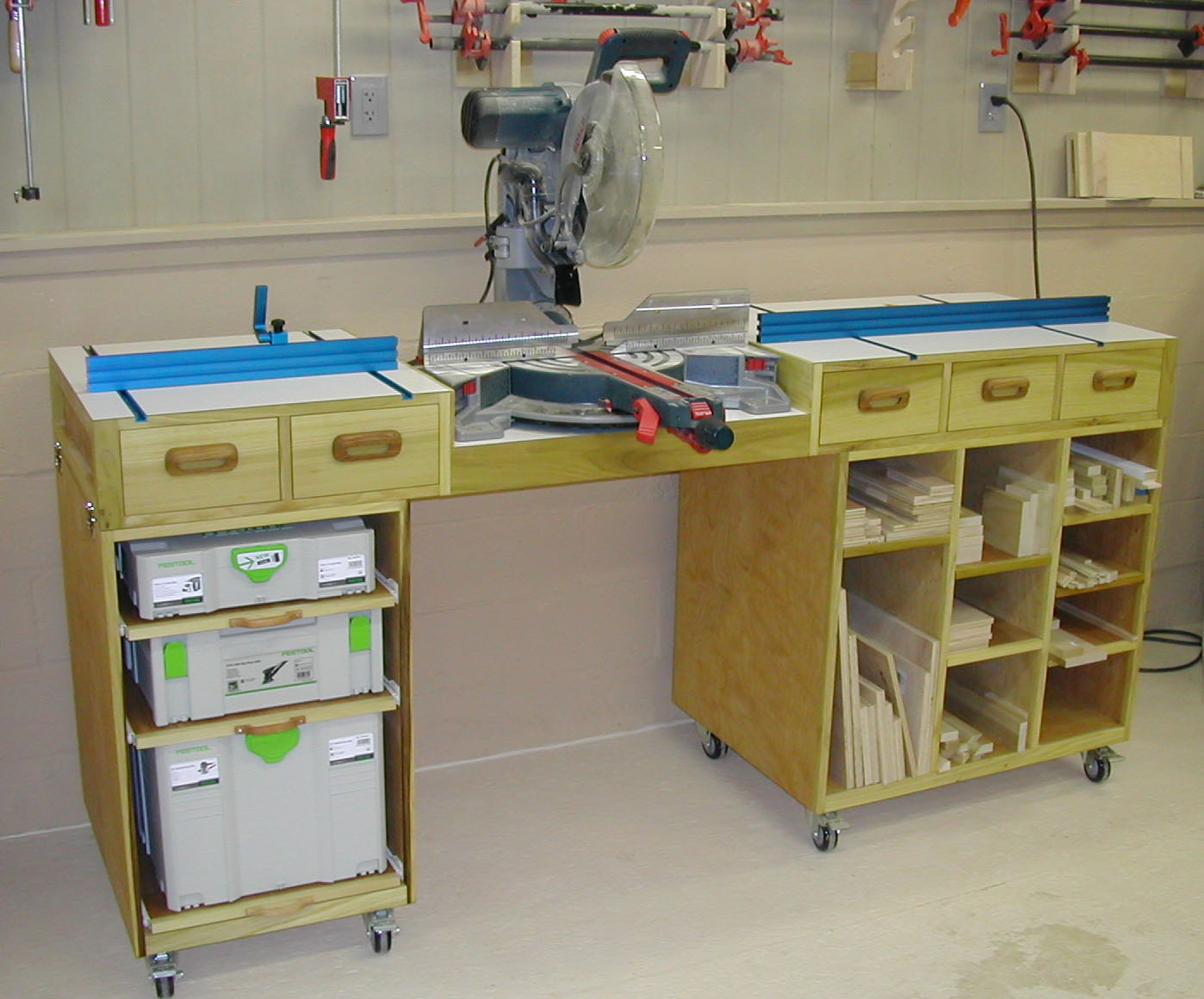
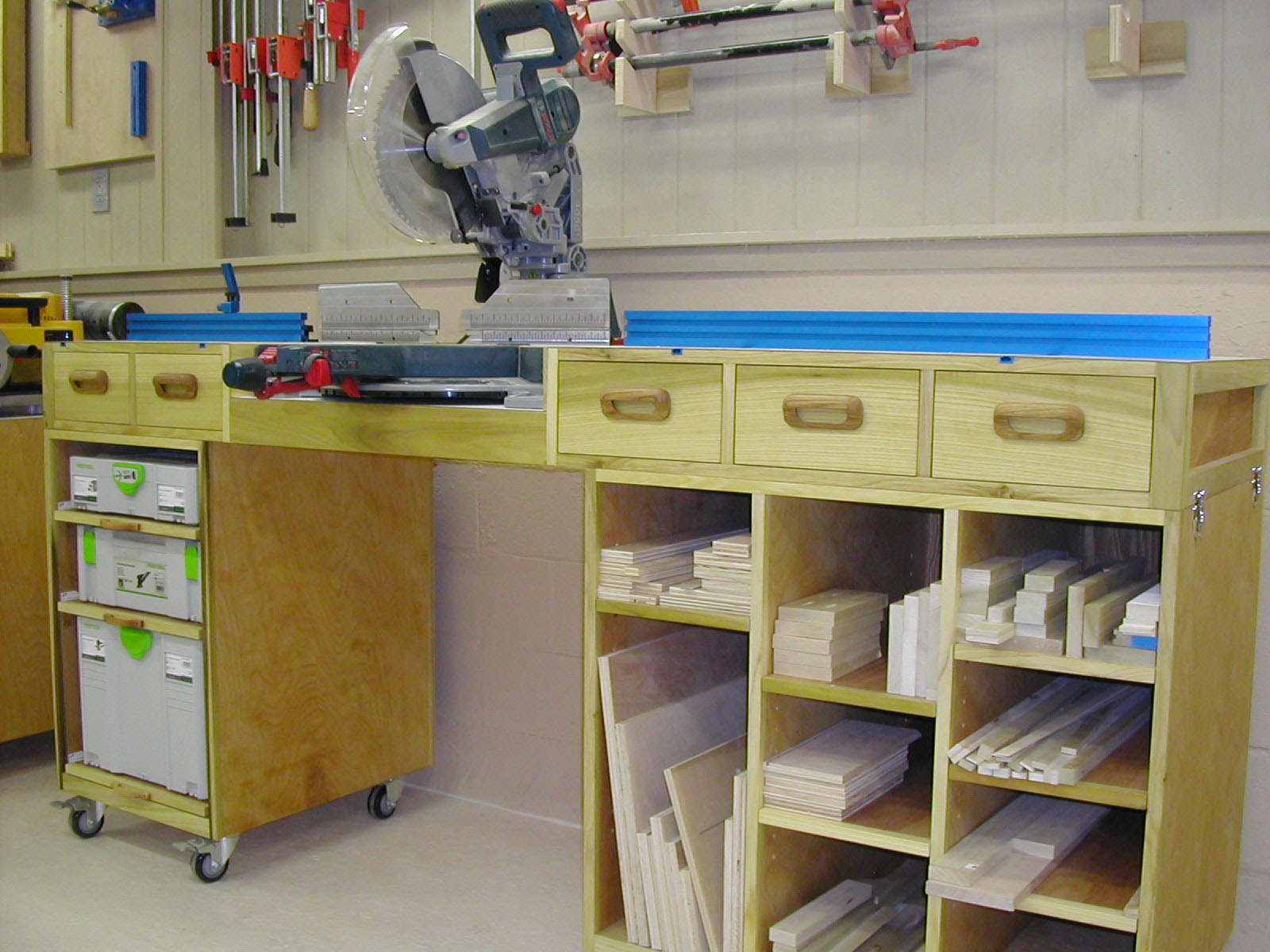
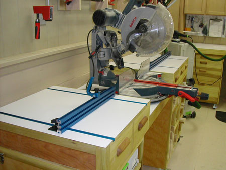
Figure 15 - The finished miter saw workstation
|
Figure 16 - Large bright work surface
|
But there is more to my impression of dramatic saw performance improvement than just reduced vibration and noise. The sawhorses were fairly steady, but they did move a bit. I've thrown 12-foot 2 X 6's on the new miter saw stand, and there is not even a trace of movement. Lean on it, bump into it, jump up and sit on it and have a cup of coffee --- there is a palpable solidity to this stand that engenders confidence and a sense of quality.
|
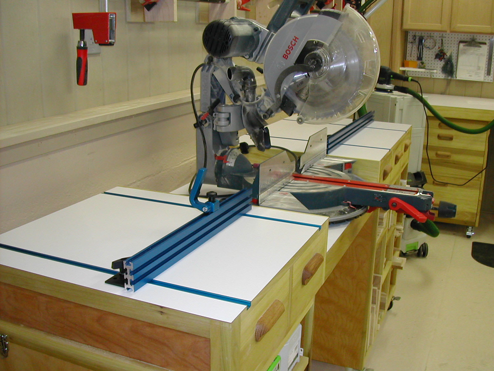
Figure 17 - Long fences and expanded work surfaces
help increase accuracy and safety
|
The long fences on either side of the work surface provide additional support, and the ability to easily add a stop for repeat cuts is a huge plus. The laminate work surface is smooth and bright and everything is easy to see. The additional storage is awesome. The working height is custom fit to my comfort, and I have already put the additional top work surface to good alternate use. All in all, I'm pleased, but there is still some work to do.
I need to recalibrate the saw, as I have noticed that it is off by about a quarter-degree from making perfect 90-degree cuts.
It is also time to install the top-notch
Forrest Chopmaster 12" X 80-tooth blade
purchased from Highland Woodworking. Years of experience with Forrest blades make me confident that this change alone will produce another quantum leap in cut quality.
|
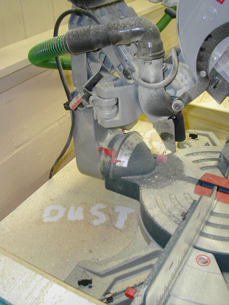
Figure 18 - The dust that escapes the vacuum
attachment on the saw is significant
|
The miter saw is hooked up right now to the
Festool CT 36
. The Festool dust extractor does a great job of collecting what dust it can, but there is still a cloud of sawdust that escapes the little chute in back of the saw and settles over the back of the miter saw stand, the wall behind, and probably in the lining of my nostrils.
So far I have built three dust hood attachments for the back of the miter saw station and none have worked the way I wanted. I am now building the fourth. Refined, and I hope perfected, if this design works well I will report to you next month.
In the meantime, if you have a miter saw perched on sawhorses, or worse, build a miter saw station. Use this design as is, modify the design, improve upon this design liberally, or go off in a completely new direction...but please, send me pictures; I would love to see them. Remember, whatever you build, it will surely be better than 2 X 6's and plastic sawhorses! Till next month...
Steven Johnson is retired from an almost 30-year career selling medical equipment and
supplies, and now enjoys improving his shop, his skills, and his designs on a full time basis
(although he says home improvement projects and furniture building have been hobbies for most of his
adult life).
Steven can be reached directly via email at
downtoearthwoodworks@me.com
.
Return to
Wood News
front page